Moog Werkstatt: adding a proper Gate input
Note: I make reference to the Moog Werkstatt schematics throughout. Copyright prevents me reposting them here; they can be found on Moog’s website.
In its original form, the Werkstatt’s own keyboard generates the Gate signal to trigger the envelope, and there is no obvious ‘Gate Input’ on the header. The existing Gate Out can be (ab?)used as a Gate In, but it’s not ideal, because as with most of these header points, anything coming in here isn’t buffered from the internal signal.
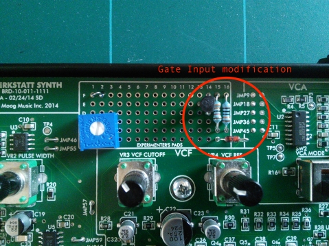
Adding a proper Gate In to the Werkstatt is straightforward enough, though a little more involved than the CV input; my approach doesn’t require the cutting of any traces, the only hack-work being the hole in the enclosure for a jack socket. It does require the end of one wire to be soldered to rather small SMT (surface-mount) components though, so you’ll need a suitably fine tip for your iron and a steady hand.
How it Works
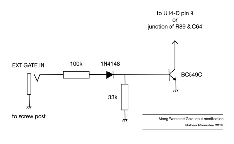
The Werkstatt’s keyboard scanner outputs a logic high at U19 pin 3 when it detects a key press. As well as stopping the scan and loading the current key value into a latch (which feeds the VCO CV), this signal is buffered to provide a Gate, and differentiated to provide a Trigger. The Key On signal is buffered inversely by the Schmitt trigger of U14-F before being flipped back positive by U14-D. In order to add our external gate without affecting any other part of the keyboard circuit, we only need to bring the input of U14-D low. In this way, we can use both the Werkstatt’s own keyboard and an external Gate without having to switch between control sources.
The solution is to use a simple NPN in saturation to take U14 pin 9 to ground when its base is taken high. In other words, a positive external Gate will take the gate inverter input low, just as does the keyboard gate detector. Because there is a diode in the way (D14), our added transistor is isolated from the keyboard scanner clock and data-bus, so there won’t be any accidental mis-readings of the keyboard CV.
Another advantage of this solution is that the Werkstatt’s own envelope retains its Gate/Trigger operating modes, as our external Gate also gets differentiated; we are activating the Werkstatt’s envelope, not over-riding it.
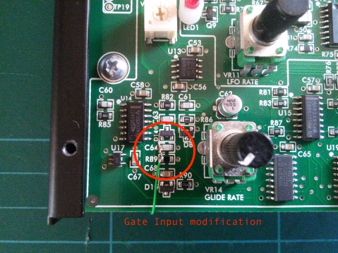
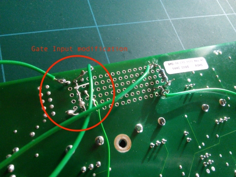
The modification takes just four components and a socket, and fits easily on the PCB. The hardest part is soldering the wire from the collector of the transistor to the appropriate point on the Werkstatt’s circuit – I chose to solder it across the connection between R89 and C64, as the two solder points make a convenient place to lay a thin wire and give it a firmer purchase.
I presume you’ll be doing both CV and Gate input mods; the socket ground can be wired to the CV In socket ground, which I wired to a solder tag around the nearby PCB mounting screw (see also the CV Input page).
*
Parts Used:
33k 1/4W 1% MF resistor
100k 1/4W 1% MF resistor
1N4148 signal diode
BC549C NPN transistor
1/8” panel mount socket
wire
These parts are what I had handy. Pretty much any NPN with reasonable gain can be used here, and the signal diode is a generic one.
57 responses to “Moog Werkstatt: adding a proper Gate input”
Trackbacks / Pingbacks
- - April 23, 2017


So, I did this one, and the CV input mod too, and it works perfectly. Thanks a lot. 🙂
I am getting a werkstatt in a couple days. I want to do this mod. I can’t tell where all the wires are going to and from in the pictures. I am not experienced in modding things unfortunately.
Hi. Sorry for the delayed reply. The minijack has two wires connected to it: input, and ground. The ground connection goes to the tag on the screw post, the input goes to the little circuit that you can see in the schematic. The emitter of the transistor, and the bottom end of the resistor, both also connect to ground. The collector of the transistor is connected to the thinner green wire in the photo, and that’s the one that goes to the surface-mount components at the bottom left of the PCB as seen in the photo. Hope that helps.
Question- I’m doing the Gate in mod today- will the mod allow the use of the EG to trigger incoming 1v/Oct for the Audio line out only, or will it also trigger the VCO out? I’m trying to patch the VCO out to the external audio in of the mother 32, and I have the M32 internal sequencer running the mother on one sequence, and a korg SQ-1 running a sequence to the Werkstatt. Without the mod, the werkstatt only sends VCO on notes the mother is sequenced to play that coincide with the CV out from the SQ-1.
The Gate input is not directly associated with the audio signal from the VCO or from the external input; it simply triggers the internal envelope. The envelope controls the VCA, which controls the volume of the audio signal fed into it. From what you describe, I gather that you want to run the Werskatt audio into the M32, yet have the Werkstatt play different notes and rhythms (please correct me if I’m wrong). I don’t know how the M32 mixes in its incoming audio, but I am guessing it’s like the Werskatt and mixes it pre-filter. When you use a Gate control, you’re not activating an audio signal, you’re only controlling its volume, and that VCA is post-filter. If you Gate the Werkstatt with the SQ-1, and run its audio into the M32, I would guess that in order to hear that you therefore need to also gate the M32 – but that would sound the M32’s oscillator. Unless you specifically want to treat the Werkstatt with the M32’s filter, is a better option to mix these two synths externally?
I should add that the VCO out is always active at full signal level; the audio out is activated by the VCA (or the Mode switch, which gates it on).
It is definitely a better option to mix the two externally, but I’m currently limited in my setup to be able to do so- my audio interface only has one input. The external input on the M32 is mixed with it’s internal VCO via a mix control pot. I was hoping to use the gate in mod to allow me to hear the cutoff/resonance EG from wersktatt through it’s VCO out.
If I understand correctly, now that I have done the mod- I should be able to do this now by just piping the main 1/4 audio out from the werkstatt into the m32 external input (I do want to apply the m32 VCF to hte incoming werkstatt).
As I wrote before, the 1/4″ audio out is post-VCA, so gated. The little “VCO out’ on the header is not gated, it’s always on, but this output is raw VCO and does not go through the filter. Which you use depends on your intentions. You’ll also have to consider the action the M32 takes on its external audio input: if it’s pre-filter, it will be gated on by the M32’s gate/envelopes and you’ll only hear the Werkstatt when the M32 is simultaneously triggered.
thank you so much for these sure fire ways… is there any way to connect a Midi 3-4 octave keyboard to werkstatt ?
also, microbrute gives out 10v gate, so, just use a
divide by 2, voltage divider or wont that work ?
many thanks ! for fantastic ways
kb
There are several small MIDI-to-CV/Gate converters available that feasibly you could build into the Werkstatt (such as http://www.midimplant.com), though I have not tried any of them and therefore won’t be providing instructions on how to integrate MIDI. I’m sure it can be done with a bit of patience.
You don’t need to divide the Microbrute gate, just plug it straight in!
hello again…Moog just emailed me that there is no Gate IN, in werkstatt, so not really recommended in long run… it seems peeple are putting stuff INTO the gate out… mmmoh wow… kb
In its factory form, that’s correct. But my mod overcomes that problem safely. That’s why I made it. 🙂
many thanks again sir !
Thanks!! It works perfectly. As easier as seems!!
Excellent. Have fun 🙂
Hi! The pitch and gate mods work perfectly. Thanks for all your work! Two questions: Can you clarify what benefits installing the filter mod confers? As far as I can tell, i can control the filter setting via CV (from a sequencer) pretty well–it seems accurate. Second: Have you looked into a mod that would allow for simultaneous outputs of the saw and square waves? Thanks to your mods, I’m incorporating my Werkstatt into a modular system, and I’d like to be able to use both waveforms simultaneously.
Hi. Are you using the minijack expander? I don’t have one of those, so the filter CV input was something I added to give me a proper connector to the outside world. As for separate waveform outputs, that’s on the list of things to do. I’ve been kept away from all this by everyday life recently, but yes, I have a few ideas lined up for the Werkstatt yet 🙂 Glad to hear you’re enjoying the synth and finding these posts useful.
Yep, i’m using the expander. so I guess that makes the filter mod redundant…sorry to hear that your life is keeping you away from synths. mine is too. it sucks.
Hey,
First of all thanks for all the documentation on your site !
I want to do this mod on my werkstatt, but my knowledge in electronics is really limited, so I don’t want to make a mistake.
I don’t have a BC549C right now, I have other NPN transistor,but I’m not sure if I can use them.
For example I have 2N3904 or BC337, can I replace the BC549C with one of those ? Or what are the important parts of the datasheet I should check to find a proper replacement ?
Thanks !
Hi 🙂 The 2N3904 would be a good alternative, as it’s a standard low-power transistor. Almost any common and cheap small-signal NPN with moderate gain will do the job. I just happen to have a lot of BC549Cs, but there’s nothing special about them in this role, and you should be able to substitute a wide range of devices successfully. The main thing to look out for if you’re working from the photos is to connect the right legs to the right places – transistors have varying pin-out arrangements. Don’t assume your replacement will slot in the same way as the 549…
Thanks, I will try that !
Hi! Many thanks for both gate and cv mods! I’ve applied them to my Werkstatt and tested it sending cv / gate from Roland JD-XA at my local music shop. Everything seems to be fine. Now I’m looking for a cheap option to route cv/gate signals from my DAW and it seems that Arturia BeatStep is the cheapest converter option out there. I’ve read a lot about it’s own sequencer issues, but I plan to use it only as a controller / converter with one midi channel to control my DAW with BSs knobs and pads and the second channel to route my midi keyboard signals to Werkstatt.
Is it critical that BS outputs CV from 0V to 7V and Gate at 8 Volts?
If you’ve already faced that piece of Arturia gear – is it a stable solution to act as a controller / converter not taking its seqencer into consideration or I’d better get a separate midi to cv/gate converter from one qc proved local synthmaker?
Hi Anton. I’ve written briefly about the Beatstep on this page. If you mean to control your Werkstatt with a Beatstep, you should be fine. The Gate In mod you’ve installed means that the BS’s Gate level is not critical; a pitch CV of 0-7V covers more octaves than many keyboards, so again you should be fine. Do bear in mind that the Werkstatt’s incoming pitch CV is added to the pitch set using the front panel control, and that any CV generated by the Werkstatt’s own keyboard is also added. If you push a button on the Werkstatt’s keyboard this gives an offset to pitch shift the incoming sequence. You can ‘prepare’ the Werkstatt before sending it a CV by pushing the button keyboard. Say, for example, that you want to play a simple sequence in and you want to pitch shift it up and down a little during playback. You could push the middle button on the Werkstatt’s keyboard and set the tuning knob to give the right pitch for your incoming CV, then during playback hit higher and lower buttons on the Werkstatt to offset the sequence in both directions. It’s quite handy.
The lowest button on the Werkstatt’s keyboard gives 0V offset, by the way.
Hi, synthnerd! Thank you so much for all this info! I think, I’ll get either Beatstep or Keystep. The additional pitch shift option is a nice feature.
The Doepfer Dark Link works perfectly for me; it converts MIDI/USB to CV.
This mod worked perfectly for me. Thanks for creating this post!
Thanks! Glad to hear it.
I did both cv and gate mods and they are exactly what i needed. I would’ve been lost without this post. Nice and simple without the need to cut tracks.
Excellent, happy to be of use!
I guess I did something wrong, or did I misunderstood something? I installed all your 4 mods on an experiment board which I mounted (correctly isolated) on the bottom. I think I did a pretty good job, but problem is my gate seems inverted. With no external signals connected, the Werkstatt gives continuesly sound. With the gate of my Microbrute connected the sounds stops once a note is pressed
Do you have any idea what have gone wrong?
Double check the transistor – make sure it’s the correct type and check its orientation – and make sure you soldered the gate mod to the right place on the Werkstatt’s PCB.
I just put this modification in to make better use of my Arturia Keystep, and it seems to work a treat! I used parts I found in my parts bin (5% resistors instead of 1%, a BC550 rather than a BC549c). Looking at the circuit, I didn’t get the impression that specific components were a necessity. Is that right?
That’s right. These are components I had lying around, and the specific values and ratings are not essential. Glad you’re happy with it!
I had a heck of a time getting the gate input to work until I realized that my transistor was not getting flipped by the base voltage change. I hooked up a multimeter and it seemed like the current drop after the 33k resistor was way too much. I pulled the 33k resistor and everything works great. Does that seem like a sane approach, or is my Moog going to catch on fire and burn the world down?
On further investigation, it appears I was using a 33 ohm resistor rather than a 33k ohm resistor. 😛
Oops 😀
I already have the CV expander for my Werkstatt, but want a proper gate in. Can I wire this up to the Gate Out jack of the expander? I never use that jack, so having it as the gate in would work for me. Thanks for the help, and the info.
The expander plugs directly into the header, so you’d need to cut the trace somewhere to wire the expander jack to your modded circuit.
Ok, thanks for the reply. I was just looking for any shortcuts since my soldering skills are pathetic and I have little confidence I can actually do this. We’ll see…
Thanks for this! I’ve done the CV input mod and it works well. Now I’ve got more components for the Gate mod – I’m missing the 33k resistor, but if I use three 100k resistors in parallel I can get equivalent to 33.3k. Would this work?
Glad to be of assistance! Don’t worry about the 33k, just use one of your 100k resistors instead. The value isn’t critical and 100k should be fine.
Hi, I had the CV, Gate and VCF mods working flawlessly using a KeyStep controller. Just plugged it in again, and now I have no gate signal. I am thinking a voltage spike killed something.
Not using any external CV/Gate/VCF inputs, here what is happening:
1) VCA ‘on’ (Drone) there is CV (pitch change) when I push a key, but no EG (decay or attack)
2) VCA off and Envelope set to ‘Sustain’: there is CV when I push a key, but no EG (decay or attack)
3) VCA ‘off’ Envelope set to EG.: Nothing… no sound. When I cycle between ‘on’ and ‘Eg’ with the envelope switch, the attack and decay settings are picked up (pushing a key)
On the scope, there is a continuous clock type signal at U19-3 and when I push a key, there is another larger signal (on the scope) showing the key being depressed and released. Same with U14F and U14E (both sides).
However, there is nothing but the clock at U14D pin 9, 8 or any pin downstream. Nothing at the Gate or trigger.
I disconnected the wire from R89,C64 (at the transistor end), and it changes nothing.
Since the CV is effecting pitch correctly, I am assuming the two CD4051 and CD4520 is operating correctly. I can take scope shots of U14-12 to verify the actual signal levels (there are hard to put a clip on). But I am stumped, unless D14 or U14 has been toasted by an overly high gate signal from the Keystep (it can do 10V gates), but I had set it to 5v
Any insight would be great.
Thank you
First up, I’m sorry you’re having problems – second, I’m afraid I can’t offer repair support here, certainly when it’s this involved. I recommend you try one of the many forums or facebook groups for this kind of thing. However, I can make a couple of quick points that might help.
When you put the VCA in drone mode, no EG activity will affect the amplitude. It just stays fixed. So don’t worry about that part of your question.
It does sound like the envelope is not triggering, and if you’re getting no activity at U14 pin 8 when you press a key on the Werkstatt, even with the Gate mod disconnected, I would guess that your hunch may be right and either U14 is partly dead or D14 is somehow at fault. Either that, or there is a bad solder point somewhere around there. This does happen. Try reflowing the solder points at that part of the circuit.
I can also say that the key-on voltage you get from your Keystep, or any other device you plug into this mod, will not have a detrimental effect on the Werkstatt. The diode in my additional circuit prevents negative peaks getting through, and the resistors prevent too much current. All the transistor does is short the input of U14-D to ground, which should not cause any problems in itself.
Beyond that, I’m afraid I have to offer my apologies and say I can’t really advise any further. Certainly, removing the mod from the rest of the circuit is the first step, and then checking the local solder points, and then checking the status of D14 and U14. Good luck!
Hi Synthnerd
Apologies as I am new to this: I have the CV done however I don’t quite know whats going on in the gate connections on the back of the board. Can you tell me what the base leg of the transistor is connected to? i can’t see because of the wire in the photo and i don’t want to assume that it necessarily goes to ground. Grateful for any light you can shed.
Hi. Thanks for pointing that out, I’d not spotted that the photo doesn’t show the legs clearly. Your answer lies in the schematic at the top of the post: the transistor base connects to the junction of the 33k resistor and the cathode of the diode. The emitter connects to ground. 🙂
Got it. Thanks so much. Can’t wait to get it running.
Got it. Thanks so much. Can’t wait to get it running.
Ok. So I did it but in the process broke R89 trying to shift a solder blob. It’s now working but the Envelope Generator isn’t working so the notes are always playing. O well…. is there a fix for that now? Gotta laugh I guess.
Oops. Yeah you’re going to want to replace that. R89 is a 10 megaohm resistor. Surface mount is not the most fun to work with…
I probably destroyed c64 in the process too. It’s a 1000pf capacitor. Surface mount also so I will bone up on technique for this replacement. It’s not the cost- it’s the time and precarious nature of it. 🙏
Hi! First, thank you for your efforts on the Werkstatt. I love the sound of mine but, even with the CV expander, it does not play well with my Arturia Keystep. As demonstrated on YouTube videos, the Keystep triggers the Werkstatt but the volume is low and it doesn’t reproduce the filter envelope triggered by the Werkstatt’s own keyboard buttons. I am assuming that this is due to my using the Gate Out as an In, although I am not certain. Can you verify that your Gate In mod would solve this problem?
In other words, using your Gate In, along with the existing exp cv in (which I presume would be the same in essence as your CV In), will sounds triggered by my Keystep sound the same (e.g., in volume, amplifier and filter envelope sweep) as sounds triggered by the Werkstatt keyboard? Thanks!
This kind of problem is exactly why I designed the Gate Input mod, yes. With this mod, any typical positive gate will trigger the Werkstatt’s envelope correctly.
As for the CV in, it’s basically a duplicate of the Exp CV but I decided to add it separately as it made sense for my setup. You may or may not decide the same, but either way I’d recommend the Gate mod for sure. 🙂
Hello,
Next to R89 and C64 on the pcb there’s two small holes where a cable could be inserted, couldn’t I just solder cable into those holes instead of onto the components?
Good question! But the answer is no, because those holes are at the other end of the components. You’d be connecting to the wrong parts of the circuit that way.
Thanks for responding.
Looking forward to doing the mod!
Many thanks for this! Just did it today and works well with the beatstep pro.
Excellent, glad you found it useful 🙂