The Korg Lambda in detail: Layering and Filtering
In previous posts, I have introduced the Lambda, and described how it generates notes and articulates them across the keyboard. The next step is to explain how those notes get to sound like different instruments. This is done by layering and filtering.
I will split discussion of this page of the schematic into two halves. This half will deal with the basics of wave layering and the fixed filters; the second half will deal with the remainder of the sound shaping at this stage.
*
LAYERING
So far in our study of the Lambda we have arrived at a point where each key gives a set of volume-articulated square waves at its respective 2′ to 16′ frequencies, and these notes are allocated to 12 signal lines: Oscs 1-3, each with 2′-16′ outputs.
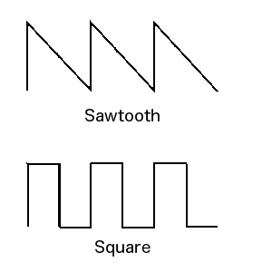
Square waves, though they are the simplest kind of divide-down wave to obtain, are not very exciting to listen to, and greater sonic variety is required if we want our presets to sound suitably different and interesting. The two basic waveforms found on most analogue synthesizers are square and sawtooth:
Without going into detail here about their harmonic content (which information can be seen clearly illustrated here, a square tends to sound woody and a sawtooth buzzy. They complement each other well. If one begins with a sawtooth (as happens most often in VCO-type analogue mono- and polyphonic synths) it is a simple matter, electronically, to generate a square wave from it. Not many synths begin with a square and thence derive other waveforms. The Lambda is one; several, but not all, other divide-down models use this approach.
We have seen in the overview how layering square waves can produce an approximation to a sawtooth wave. Below is an illustration of the result of this process. Electronically speaking, this is achieved by summing op-amps (ICs 2 and 4-7 on the schematic) which use proportional resistor values to sum the incoming squares at particular ratios. For example, Mi (Osc 1) 16′ is fed to IC4 via a 100k resistor, and its 8′ is fed to the same via a 200k resistor. Thus the 8′ output of Osc 1 is present at half the level of its 16′ output. Its 4′ output is fed through via a 390k resistor, which is near enough to giving a quarter of the 16′ level, and so forth across the oscillators and their respective 2′ to 16′ lines.
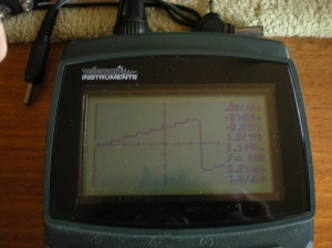
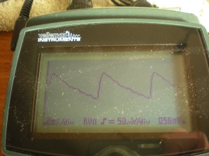
The first photo shows the signal at Test Point 23 on the schematic. This is the summed pseudo-sawtooth described above. Note I have stretched the waveform to more clearly show the steps. As it is derived from four proportionally-summed square waves, there are 16 steps in total forming the pseudo-sawtooth, though not all are visible in the image:
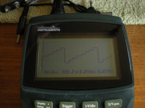
The next photo shows the signal at Test Point 35, again a summed pseudo-sawtooth from Mi, this time using only three of the four octave footings. Note how the reduction from four to three summed squares produces a much rougher, more notably stepped waveform:
If we follow the paths of all the summed square waves at this point in the Lambda, we can see that the purpose is to provide differently shaped waveforms, built from a combination of squares at different frequencies, that are suitable for use as the basic raw tones of particular preset sounds. These paths are visible on the schematic, and though they appear convoluted, it is possible to separate out the waves from which each preset should be derived and, in the event of a fault such as a TOG failure, to use this information to isolate the defective oscillator/s.
*
FILTERING
Once the waves are summed, they are passed to fixed filter banks. Each filter bank represents one preset sound, except in the case of the Organ preset, which uses three parallel filters, and the Brass, which has its own voltage-controlled filter (VCF). More on that shortly. First, the fixed filters.
I will not here go into the technical details of how a filter works. Illustration can be found elsewhere on the matter, so I’ll simply state that the purpose of filters in analogue synthesizers tends to be to remove harmonics – start with a harmonically rich sound, smooth out harmonics below/above/around a certain frequency (the cutoff), and by the use of feedback boost at that frequency in a controlled way (resonance or Q). Harmonic content is one of the major determining factors in how a sound actually sounds, and this is one way to govern it that is easy to achieve in analogue electronics.
Fixed filters exist for the Strings II, Strings I, Chorus, and Organ presets in the Ensemble section. In the Percussive section, fixed filters exist for the Electric Piano, Clavi, Piano, and Harmonics. There is also a fixed filter for the Key-Click, a sound that is not switchable independently, but which is mixed with its own volume control into the Electric Piano sound. It is generated by filtering the key-trigger circuit output that provides a short pulse whenever a new key is pressed. The trigger circuit is used for other things too, more on which later.
The filters are broadly very similar across the set: they are a mixture of 2nd-order (ie. 2-pole, or 12dB) low- and high-pass active filters using RC networks and op-amps. Filter design and topology will not be elaborated upon here, but suffice to say the filter banks provide adequate tone-shaping to individuate the various sounds, despite them sharing their originating material.
Though the filters are fed from common sources in varying amounts, their outputs are switched on a per-preset basis and the combined switched-in signals are summed by another op-amp, one in the Ensemble section and one in the Percussive section. Thus, for example, the output of the Strings II filter bank has a simple open/closed switch to include or exclude it from the mix input of IC25, as do the Strings I and Chorus filter banks, while the Organ is derived via three parallel filter banks that are mixed passively using resistors before being collectively switched into the Ensemble mix. The same procedure is followed for the Percussive section. IC25 provides, on pin 1, the combined Percussive signal, and on pin 7, the combined Ensemble signal.
*
ADDITIONAL INFORMATION:
WAVEFORMS BEFORE AND AFTER FILTERING
Considering the rather rough stepped waveforms illustrated above, one might think the Lambda’s raw waves would sound too brash; the sharp edges of the steps are manifest as high-frequency content, and especially in the lower registers can effect a kind of aliasing tone, where one hears a high-pitched background whine behind the desirable tonal content that is likely to be displeasing, even distracting. It should be noted, however, that this is not necessarily a problem, as the Lambda’s filters remove much of the undesirable content from these stepped waves.
Below is an illustration of the signal at Test Point 26. I have isolated Miii so there is only one oscillator output present here. This is the input to the Strings II filter, played somewhere near the middle of the keyboard. Note the obvious stepping:
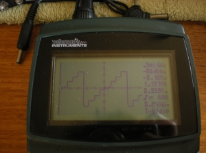
The subsequent filter removes frequencies below and above a certain window; note in the next illustration how the steps have been smoothed as the high frequency content is reduced (to put it more simply, the sudden jumps are ‘slowed down’ to a more gentle slope):
Three points to note here: firstly, the smaller steps are smoothed to a kind of slightly wavy slope, so although the harshness is gone, there will still be a slightly discernible brightness to the audio signal present as a quiet multiple of the fundamental of the note played; secondly, the falling edge of the sawtooth is also slowed to a slight slope, which is here the leading edge, and which leads to point three; that the waveform is inverted from the original, flipped upside down by the activity of the op-amp buffer IC25. This reading was taken at TP 48. Inversion has no effect on the audible content.
Due to the fixed cutoff points of these filters, low notes will exhibit more artefacts than high ones. With the user-adjustable filters wide open and the lowest notes played, some of these, though reduced, are still present; whether this is a problem depends on how one likes to use the Lambda.
*
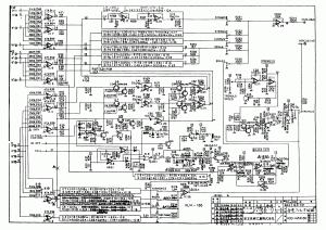
Here is the page of the service notes that both this and the next post deal with:
In the next post I will discuss the remainder of the KLM-186 board as depicted on this page of the schematic.
